

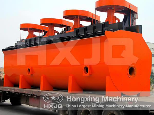
Flotation Machine
Flotation machine, which is also called flotation separator, is applied for separating nonferrous metal and ferrous metal and nonmetal such as fluorite and talc.

Flotation machine is suitable to separate non-ferrous black metals, and separate nonmetal, for example, coal fluorite e, and talc. Flotation machine vacuum formed with centrifugal which is formed because of the moving of impeller rotation driven by V-belt drive of the motor, On the one hand inhaling enough air and mix the air with pulp. On the other hand stir the slurry and mix it with other drugs. At the same time, refine foam so that the mineral can cohere on the foam. So the mineral float to the surface of slurry and then form mineralized bubbles. Adjust the height of the disc and control the liquid level to scrape the useful foam out by scraper.
1. Flotation machine is with large inspiratory capacity and low energy consumption;
2. Horizontal arrangement, foam pump is needn’t;
3. The peripheral speed of the impeller is low. The life of impeller cover is long. Pulp recycles in two opposite directions at a fixed manner, which helps coarse mineral suspensions.
When flotation machine works, slurry is inhaled from the bottom of the trough to the space between impellers. Meanwhile, the low pressure air sent by fan is sent to this area through the air distributor in the hollow shaft. After sufficient mixing, the slurry is pushed out by the impeller, and then goes to the whole trough. When the froth rises to the stable level, after the enrichment processing, froth overflows to the froth trough from the overflow weir. Another part of ore slurry flows to lower part of impeller for the remixing with air. The remaining slurry flows to the next trough until it becomes residue.
| Model | Trough cubage (m³) |
Inside dimensions (L×W×H) (m) |
Air suction amount (m³/㎡·min) |
Power (kw) |
Motor model | Processing capacity (m³/min) |
Single trough weight (kg) |
| BF-0.37 | 0.37 | 0.74×0.74×0.75 | 0.9~1.05 | 1.5 | Y90L-4 | 0.2~0.4 | 470 |
| BF-0.65 | 0.65 | 0.85×0.95×0.9 | 0.9~1.10 | 3.0 | Y132S-6 | 0.3~0.7 | 932 |
| BF-1.2 | 1.2 | 1.05×1.15×1.10 | 1.0~1.10 | 5.5 4.0 |
Y132M2-6 Y132M1-6 |
0.6~1.2 | 1370 |
| BF-2.0 | 2.0 | 1.40×1.45×1.12 | 1.0~1.10 | 7.5 | Y160M-6 | 1.0~2.0 | 1750 |
| BF-2.8 | 2.8 | 1.65×1.65×1.15 | 0.9~1.10 | 11 | Y180L-8 | 1.4~3.0 | 2130 |
| BF-4.0 | 4.0 | 1.9×2.0×1.2 | 0.9~1.10 | 15 | Y200L-8 | 2~4 | 2585 |
| BF-6.0 | 6.0 | 2.2×2.35×1.3 | 0.9~1.10 | 18.5 | Y225S-8 | 3~6 | 3300 |
| BF-8.0 | 8.0 | 2.25×2.85×1.4 | 0.9~1.10 | 22 30 |
Y225M-8 Y250M-8 |
4~8 | 4130 |
| BF-10 | 10 | 2.25×2.85×1.7 | 0.9~1.10 | 22 30 |
Y225M-8 Y250M-8 |
5~10 | 4660 |
| BF-16 | 16 | 2.85×3.8×1.7 | 0.9~1.10 | 37 45 |
Y280S-8 Y280M-8 |
8~16 | 8320 |
| BF-20 | 20 | 2.85×3.8×2.0 | 0.9~1.10 | 37 45 |
Y280S-8 Y280M-8 |
10~20 | 8670 |
| BF-24 | 24 | 3.15×4.15×2.0 | 0.9~1.10 | 45 | Y280M-8 | 12~24 | 8970 |
To send inquiries, including feedback, requests for information, or questions, you may use our Feedback and Inquiries form below.
Fields marked by an asterisk (*) are required fields.